Plants on the Mind
2024
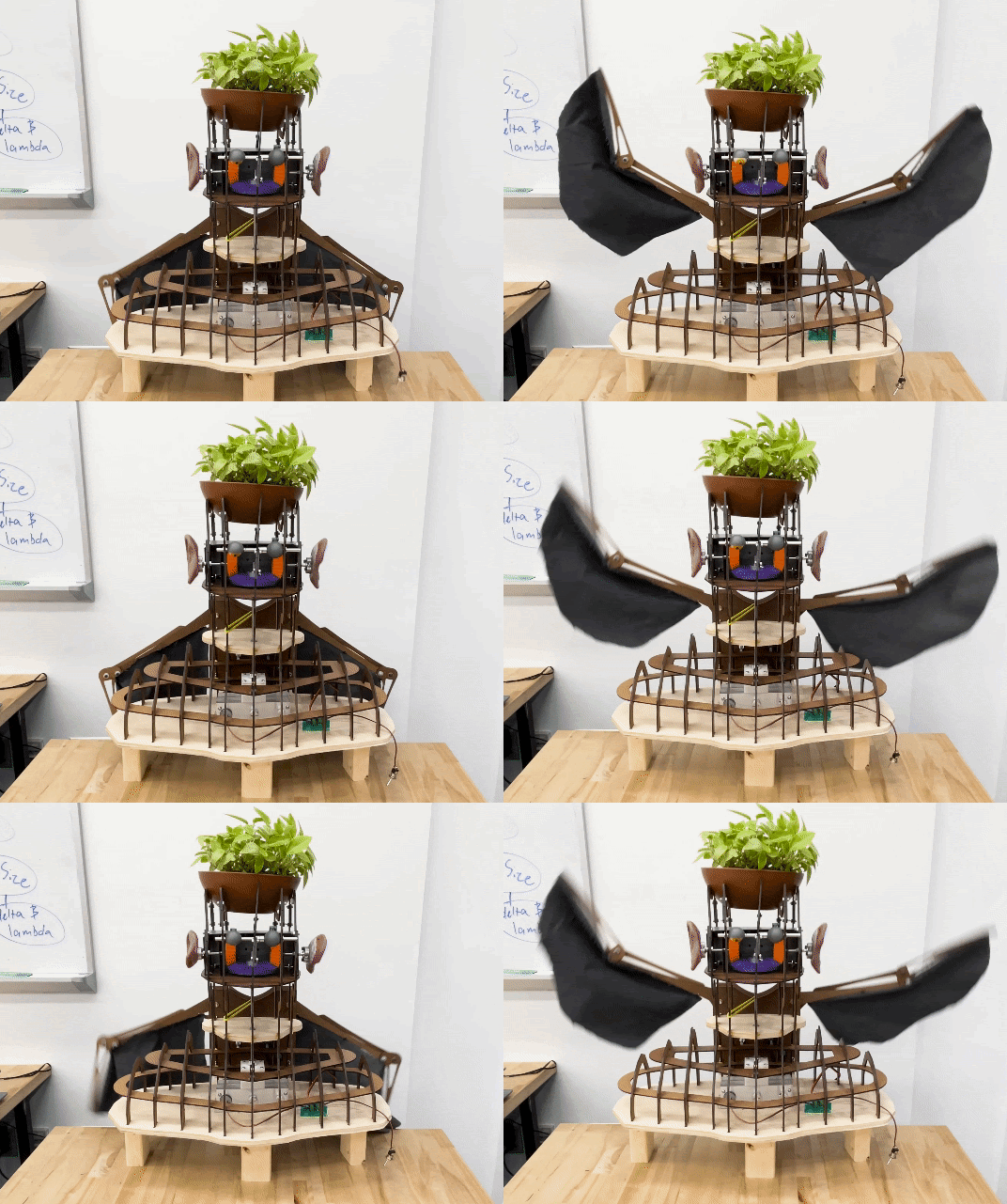
A plant themed kinetic sculpture.

Context
- Course: Intro to Mechanical Prototyping (ENGR 2330)
- Project Prompt: “Design and build a kinetic sculpture using multi-planar mechanisms powered by a single electric motor”
- Timeframe: 4 weeks
- Team Roles: Project Manager, CAD Designer, Fabrication
- Year: Spring 2024
Process
For the final team project for Introduction to Mechanical Prototyping (MechProto), I wanted to create an exciting kinetic sculpture that integrated motion in several planes and axes. After some brainstorming, my team set out to make a kinetic sculpture inspired by humanoid potted plants that position the plant as the ‘hair’ of the figure.
The final sculpture contained the following motion systems:
- Blinking Eyes - utilizes a three-bar linkage to repeat the motion of an eyelid rotating along an axis
- Spinning Ears - resin 3D printed realistic human ears spin in opposite directions via a differential gearbox
- Flapping Wings - wings flap up and down in a repeating motion inspired by the bone structure of birds
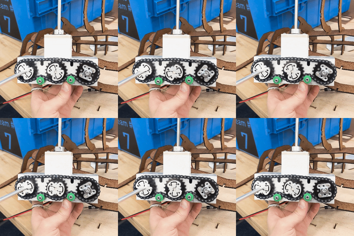
- Core Gearbox - transfers motion from a single motor to the differing axes of rotation for each other mechanism


Over the course of the 4-week project, I focused on creating a functional yet aesthetically pleasing frame for the sculpture, along with mechanically integrating each system.
Early on in the project, the initial frame was created as the starting point for the detailed design of further mechanisms that depend on the geometry of the frame. I created the frame of the sculpture by outlining sectional views of a low-poly model of a human bust in Fusion360:


This was done from two directions to create an arrangement of intersecting layers. Where a layer intersected with another layer, an indent was added to both components to create a joint:

Each piece for the frame was laser cut out of 3/16in High Density Fiberboard, and the appropriate tolerances were used.

As further details developed in our designs, more changes had to be made to the frame to accommodate things like bearing spacing, mounting points, etc. I tackled all these issues at once by redesigning parts of the frame within the context of the other mostly finished systems. I added things like mounting holes and split parts of the frame into more pieces to allow for physical assembly.

The core gearbox is the part of the sculpture that provides rotational power to each other mechanism. The gearbox itself uses a central chain drive from the DC motor to distribute power to two other shafts. One of these shafts goes to the wing mechanism, and the other goes up to the head via a set of bevel gears.

The two pieces of aluminum U channel that serves as the main structure for the gearbox were manufactured on a manual mill. After designing the gearbox in SolidWorks, I created a technical drawing to help me drill each hole with precision.


Reflection
This project was the final of a series of awesome learning experiences for me in MechProto. By the end of this project, I had learned about the struggles of collaborative designing and how to work through them. I also delved into the intricacies of mechanical integration and version control.
I’m proud of what my team and I created, and it can still be found on display in Olin’s Academic Center hallway (although it now lacks any plant hair).
